This page contains improvements to the AWR Design Environment for module designers.
License requirements: Layout with iNets (MWO-XX6+)
Leverage the power of AXIEM in the Cadence Virtuoso RF Solution.
|

|
|
|
|
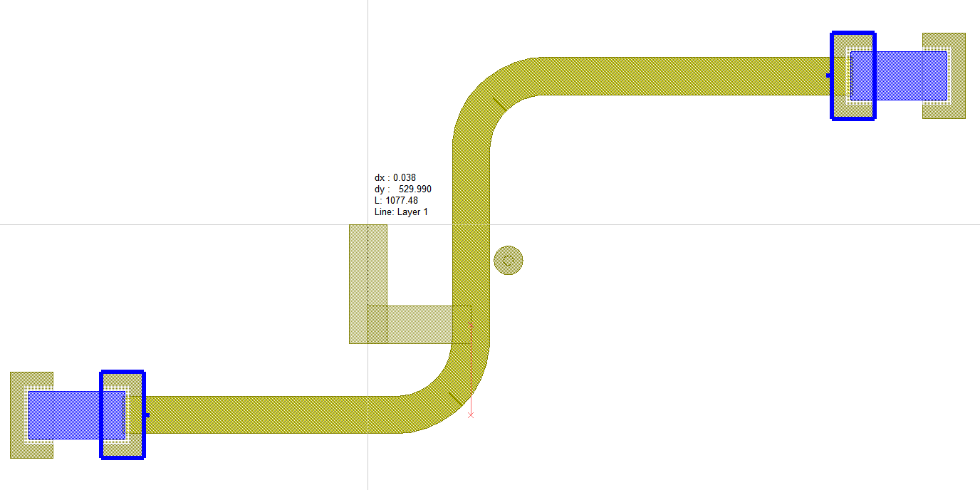
Easily modify existing iNet routes using the Reshape Route command.Reshape RouteThe project will open to an iNet routed too close to a via.
|
|
|
|
|
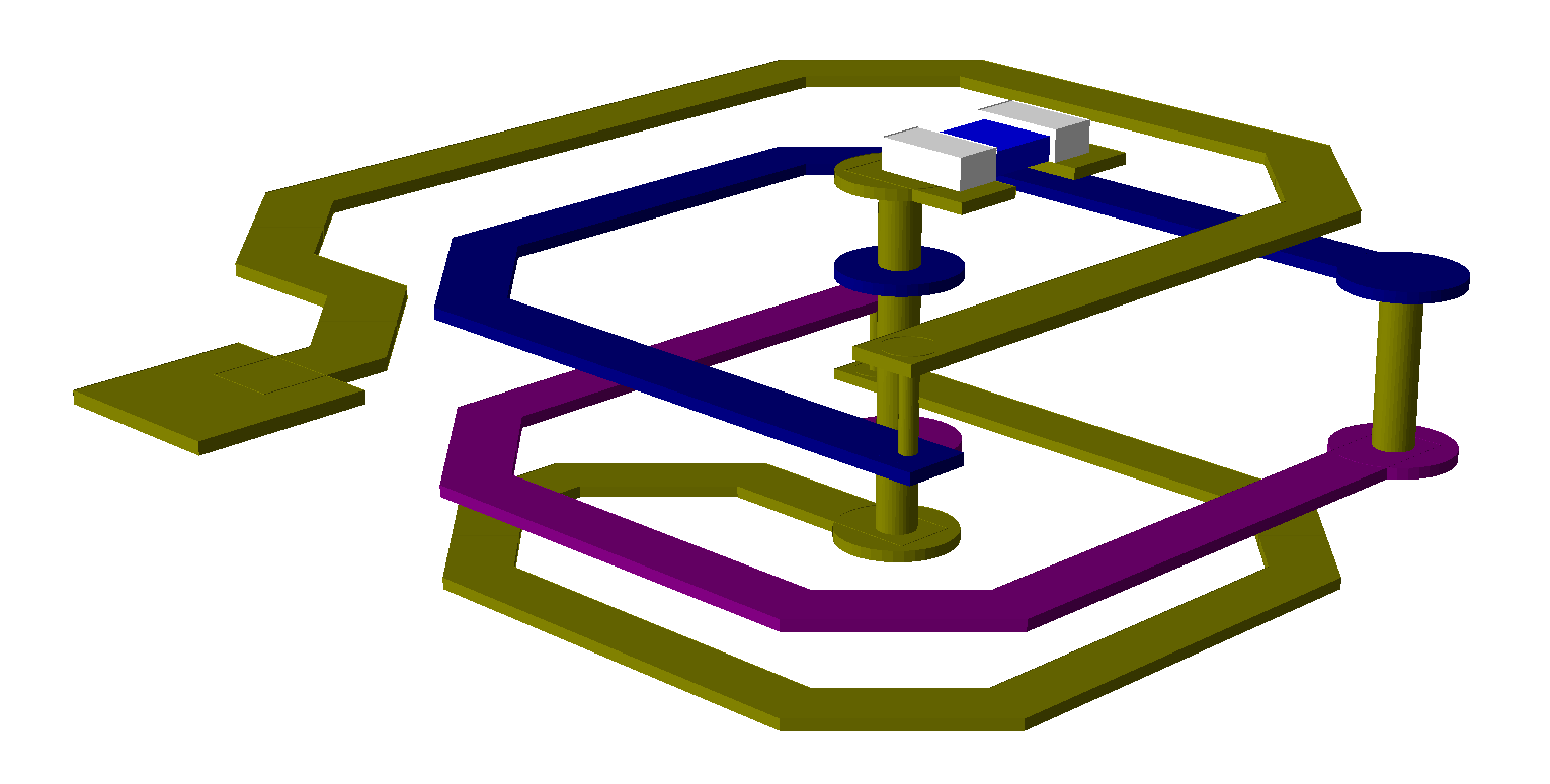
Route iNet bends with new bend styles.Chamfered and rounded bend stylesThe project will open to a Schematic Layout with an iNet spiral module inductor
|
|
|
|
|
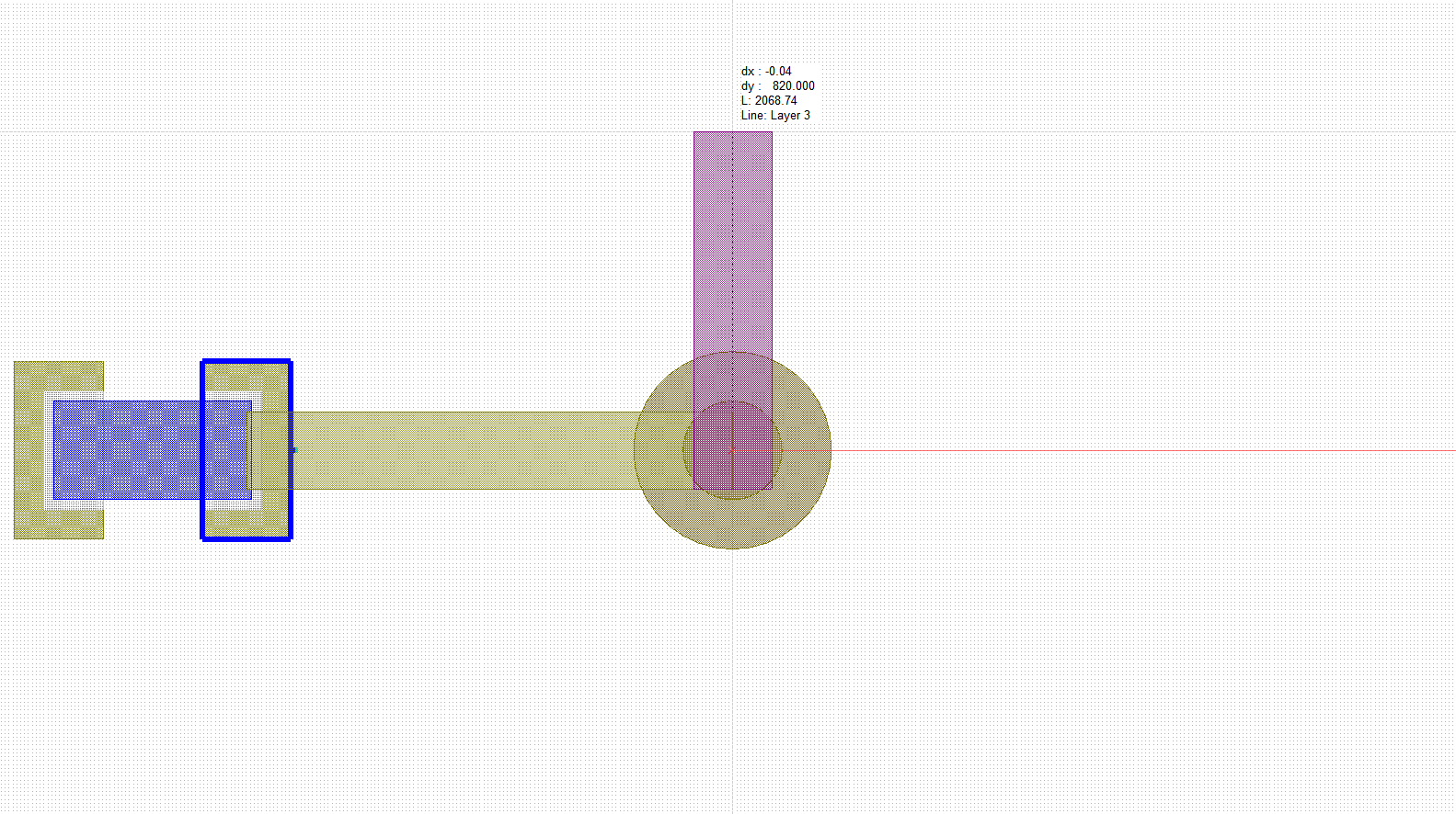
Change iNet via types on the fly.Change iNet vias with hot keyThe project will open to a Schematic Layout with an un-routed iNet (ratline)
|
|
|
|
|
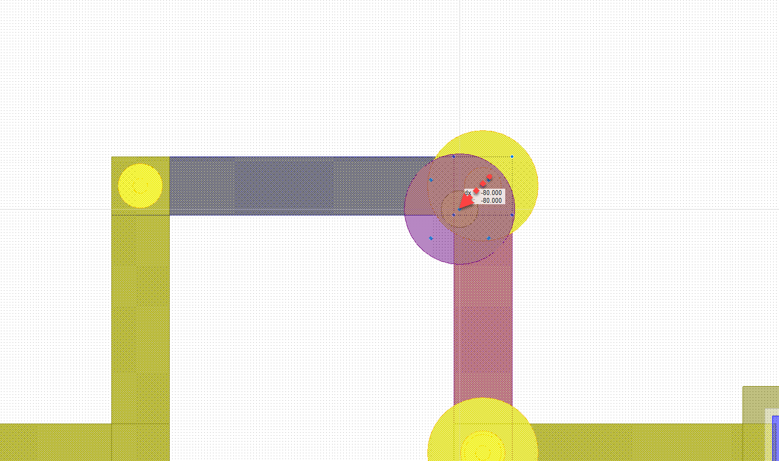
Manually move iNet vias.Move iNet viasThe project will open to a Schematic Layout with an iNet and vias in their default locations.
|
|
|
|
|
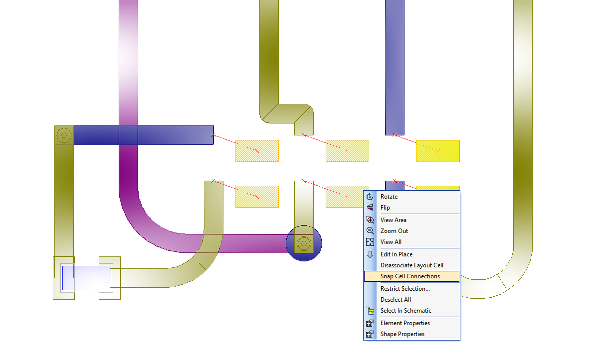
Auto-reconnect disconnected iNet routes.Snap cell connectionsThe project will open to a Schematic Layout with several iNet routes connected to all six pins of an SMD footprint.
|
|
|
|
|
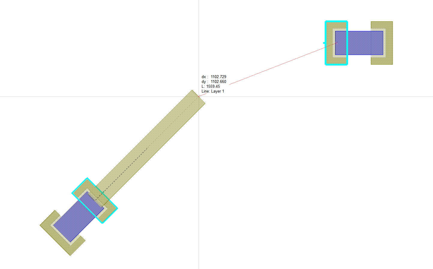
Start iNet routes orthogonal to any pin.Orthogonal startThe project will open to a Schematic Layout with an un-routed iNet (ratline) with one of the cells rotated 45 degrees.
|
|