Go to playground home.

Schematic

This page contains improvements to the Circuit Schematic and System Diagram editors in the AWR Design Environment.


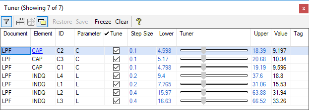
Tune on an unlimited number of variables in an amazingly compact, yet readable dialog.

New Tuner

The demo opens the lpf_lumped example, simulates, and opens the tuner.

  1. Tune on any of the variables.
    • Click and drag on the slider for the variable you want to tune on.
    • Select the slider and use the arrow keys to move one step at a time.
  2. Filter on any column by typing in the text area under each column header.
    • Note that hovering over the toolbar buttons pops up balloon help with descriptions about the button function.
    • Make sure filtering is enabled by clicking the Filter toolbar button
  3. Click on any entry in the Element column to show the Circuit Schematic and Element being tuned.

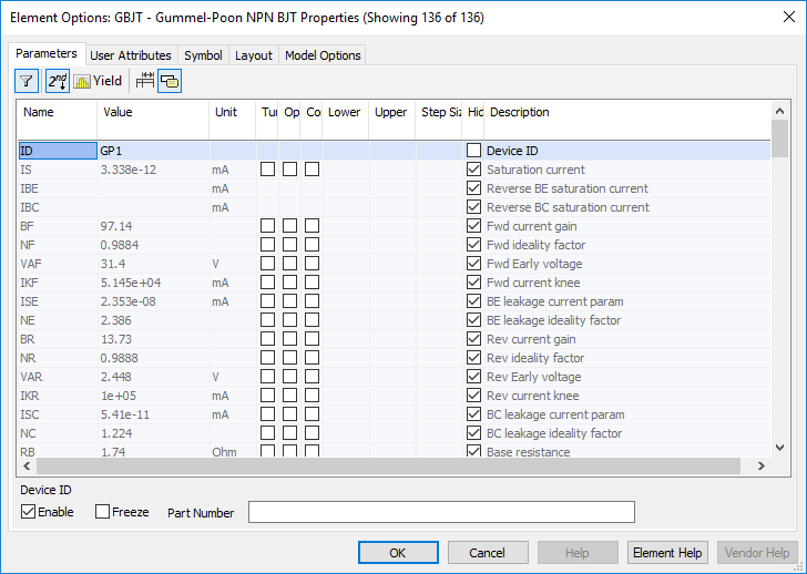
Filter, group edit, and spend less time changing tabs in the new element parameters dialog

New Element Parameter Dialog

This demo opens the nonlinear_example project, opens the IV_Curve Circuit Schematic, and opens the element properties for the transistor.

  1. Note that hovering over the toolbar buttons pops up balloon help with descriptions about the button function.
  2. Enable the secondary parameters by clicking the 2nd toolbar button.
  3. Filter on a parameter name by type in the Name column.
  4. Sort parameters by clicking any of the column headers.
  5. Multi-select by holding CTRL and selecting multiple parameters.
    • This is useful for enabling tuning or optimization on sets of variables.
  6. Show yield settings by clicking the yield toolbar button.
  7. Auto-size column widths by pressing the auto-size toolbar button.

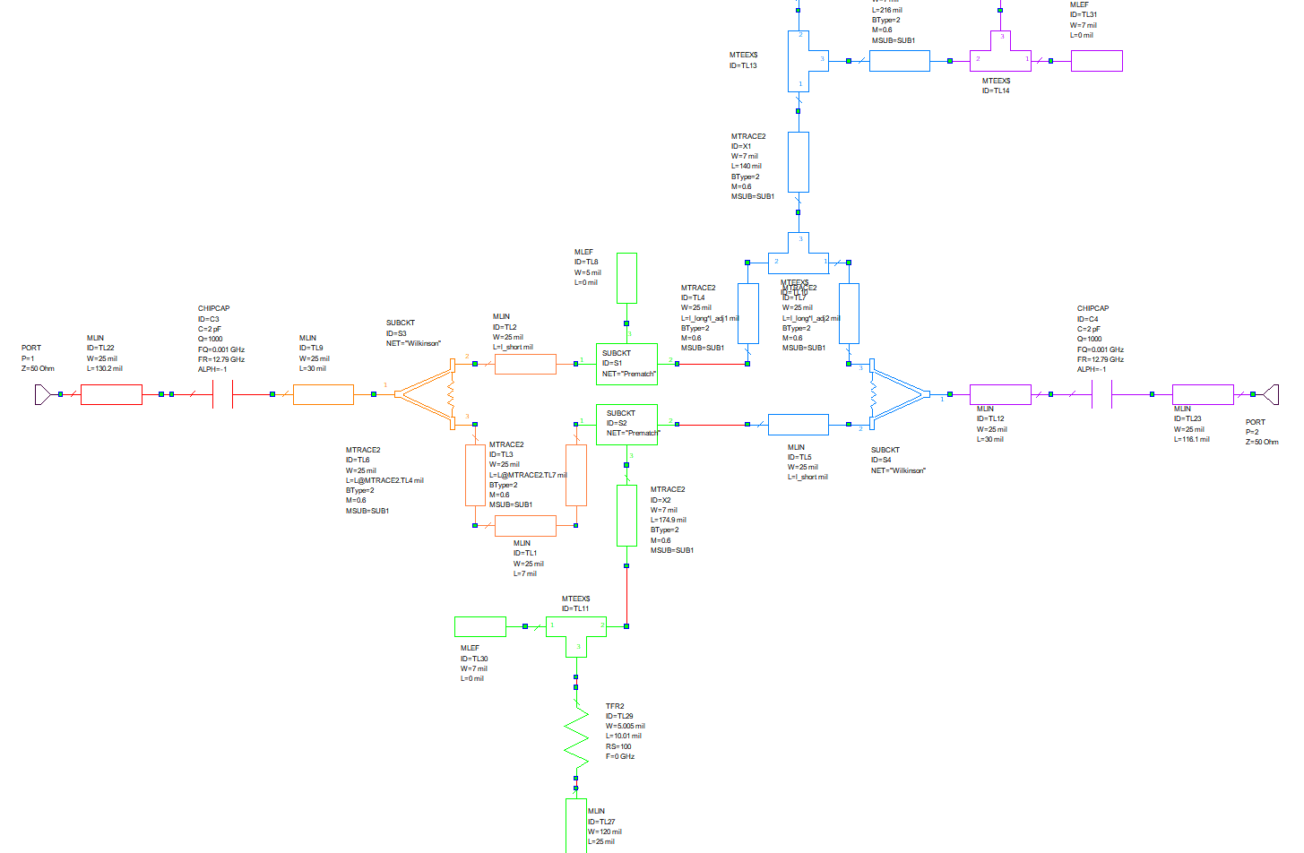
Customize your schematics' appearance with infinite symbol colors

Easily identify schematic elements without zooming in.


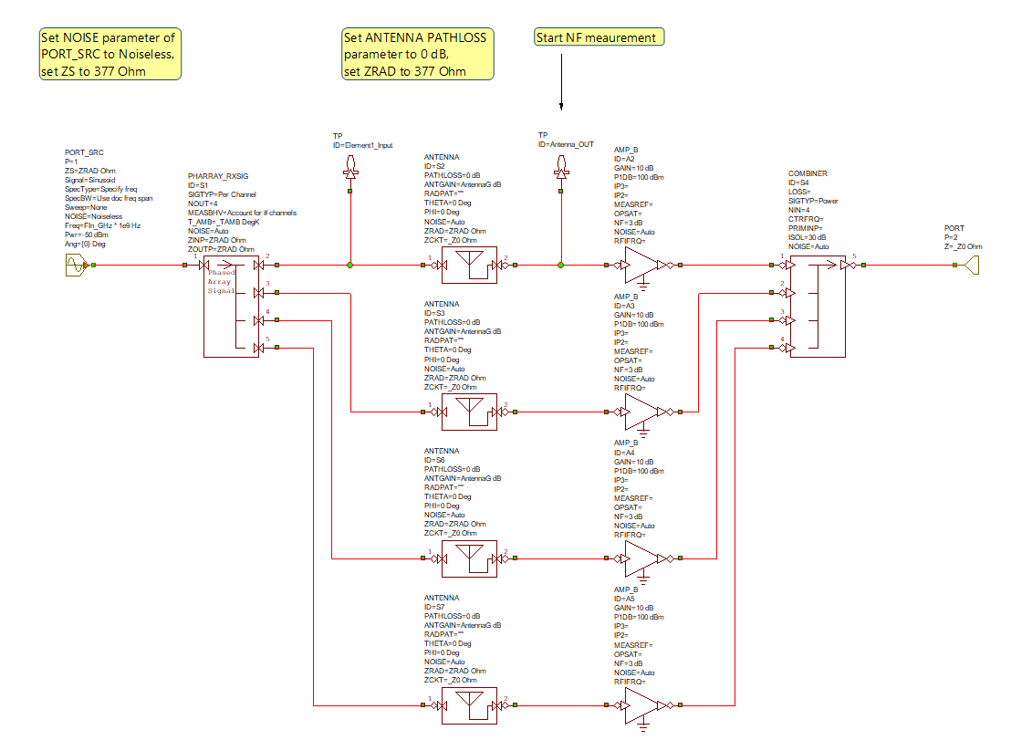
Quickly and easily create complex System Diagrams with Buses

VSS Bus Support

This demo opens the project, displays the proper System Diagrams and Graphs, and then simulates.

  1. Note that the Reference System Diagram shows a 4 channel Phased Array simulation wired the traditional way.
  2. Note that the Array with BUS models System Diagram shows the same 4 channel Phased Array simulation wired with buses and vector instances and is significantly more simple.
  3. Note that the both tables show the same answer which illustrates that both System Diagrams are electrically equivalent.
  4. Further details can be found in the Design Notes in the project.