Go to playground home.

Antenna

This page lists improvements to the AWR Design Environment for antenna designers.


Easily Quantify and Optimize Antenna Performance Metrics
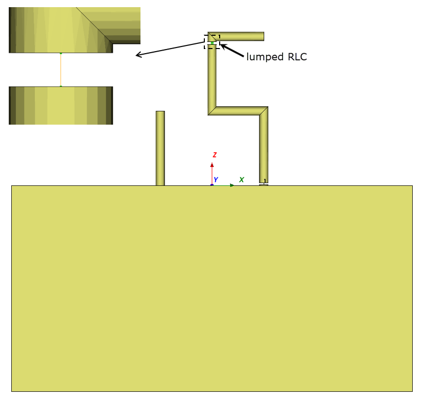
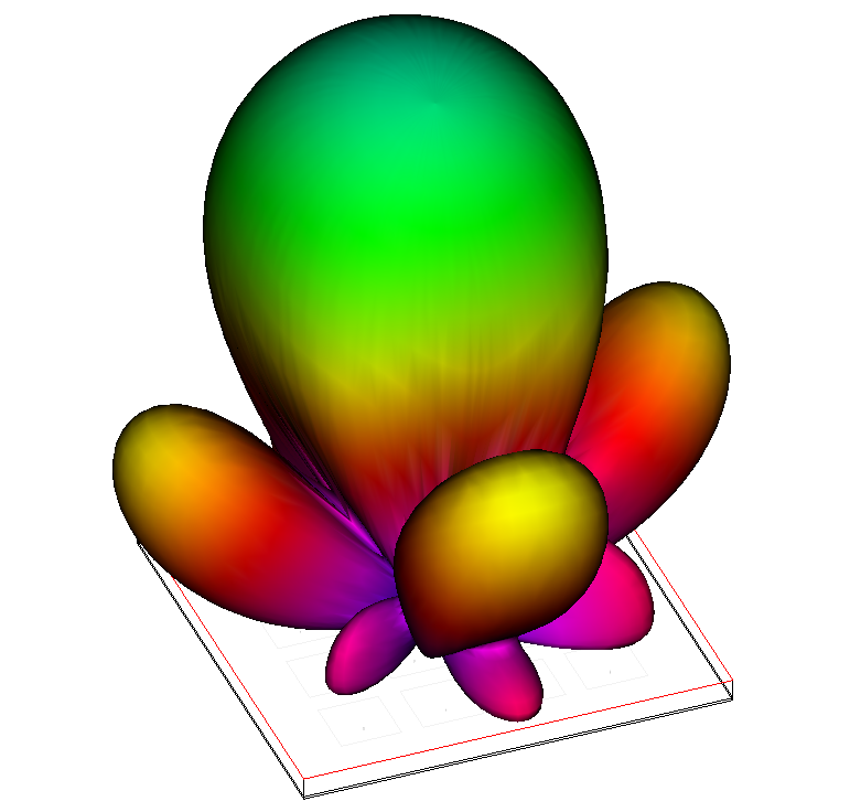

Analyze antenna performance

The project opens and simulates a 4x4 path array antenna.

License requirements: Layout and AXIEM (MWO_105+, XEM_001, XEM_100 or TOK_100)
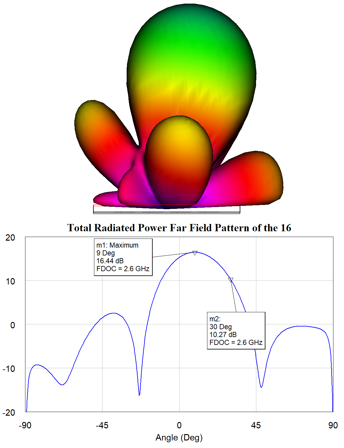
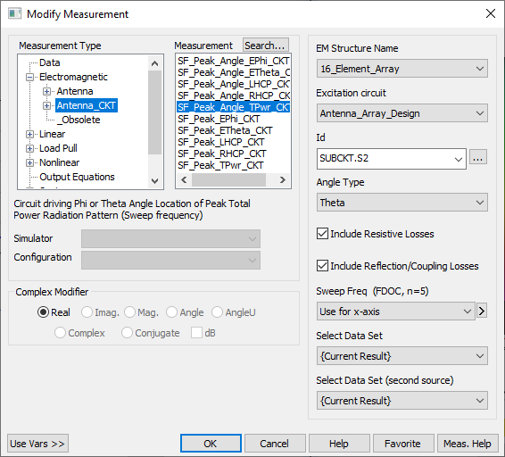
  1. In the "Principal Plane Cut Total Power" graph; note the principal plane cut; the steering angle (theta) is 9 degrees at 2.6 GHz.
  2. Rotate the 3D View of the antenna so the orientation matches that of the Principal Plate Cut Total Power by pressing the Back button on the EM 3D Layout toolbar.

Learn about new PEAK measurements

An additional graph opens which contains a measurement for the theta angle of peak power.

  1. In the "Peak Theta Versus Frequency" graph legend, right-click the Peak Theta measurement and choose Modify Measurement.
  2. Note the new class of PEAK measurements. These dimension-reducing measurements allow you to analyze antenna performance across a frequency range.

Change the theta angle with optimization

An optimization goal is added to the "Peak Theta Versus Frequency" graph.

  1. The current peak theta angle is 9 degrees. The optimization goal is set up to steer the beam to 45 degrees.
  2. The voltage magnitudes and phases presented to the antenna are set up to be optimizable.
  3. Set the Optimization Method to Discrete Local Search and the Maximum Iterations to 50.
  4. Click the Analyze button before proceeding to ensure the 3D patterns update during optimization.
  5. Click Start on the Optimizer and watch the antenna pattern shift from 9 degrees to 45 degrees.
  6. NOTE: The variables being optimized are in a schematic which is driving the EM structure. The resulting antenna patterNs are dependent on the voltage magnitudes and phases presented to the EM structure from the schematic.

Directly Simulate and Model within an Antenna

  • Directly simulate antenna loading, matching networks, and model frequency-dependent circuit components within an antenna
  • Simulate matching networks that are embedded in the antenna without the need for additional ports and circuit simulations.
  • Model frequency-dependent components in the antenna simulation to design reconfigurable or more broadband antennas.