Go to playground home.

Phased Array Design

This page lists new capabilities in the AWR Design Environment for phased array designers.

License Requirements: VSS Time Domain and the 5G or Radar Library (VSS_250+, W5G_100 or RDR_100)


Efficiently Design, Configure and Simulate Phased Array Systems

Use Buses to Simplify Implementation of Various Phased Array Architectures

Examples include Digital or Hybrid Beamformers
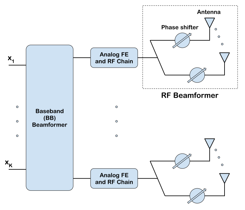

Hybrid Beamforming Example

The project shows a partially-connected hybrid beamforming architecture, illustrated in the figure on the right.

  • In this example, a 32-element rectangular phased array (16x2) is implemented using buses.
  • The array uses 8 RF links, each of them driving 4 antenna elements.
  • The bus implementation allows for hierarchical designs, building RF links as a bus with 8 components, and then using a bus with 4 components where each of them refers to the RF links.
  • The bus-handling blocks in VSS support conversion of buses to serialized components and vice versa, allowing you to build complex architectures.
  • The combined 32 elements are then fed into a PHARRAY_F block, which applies the proper phase shifts depending on the element position and steering angles.

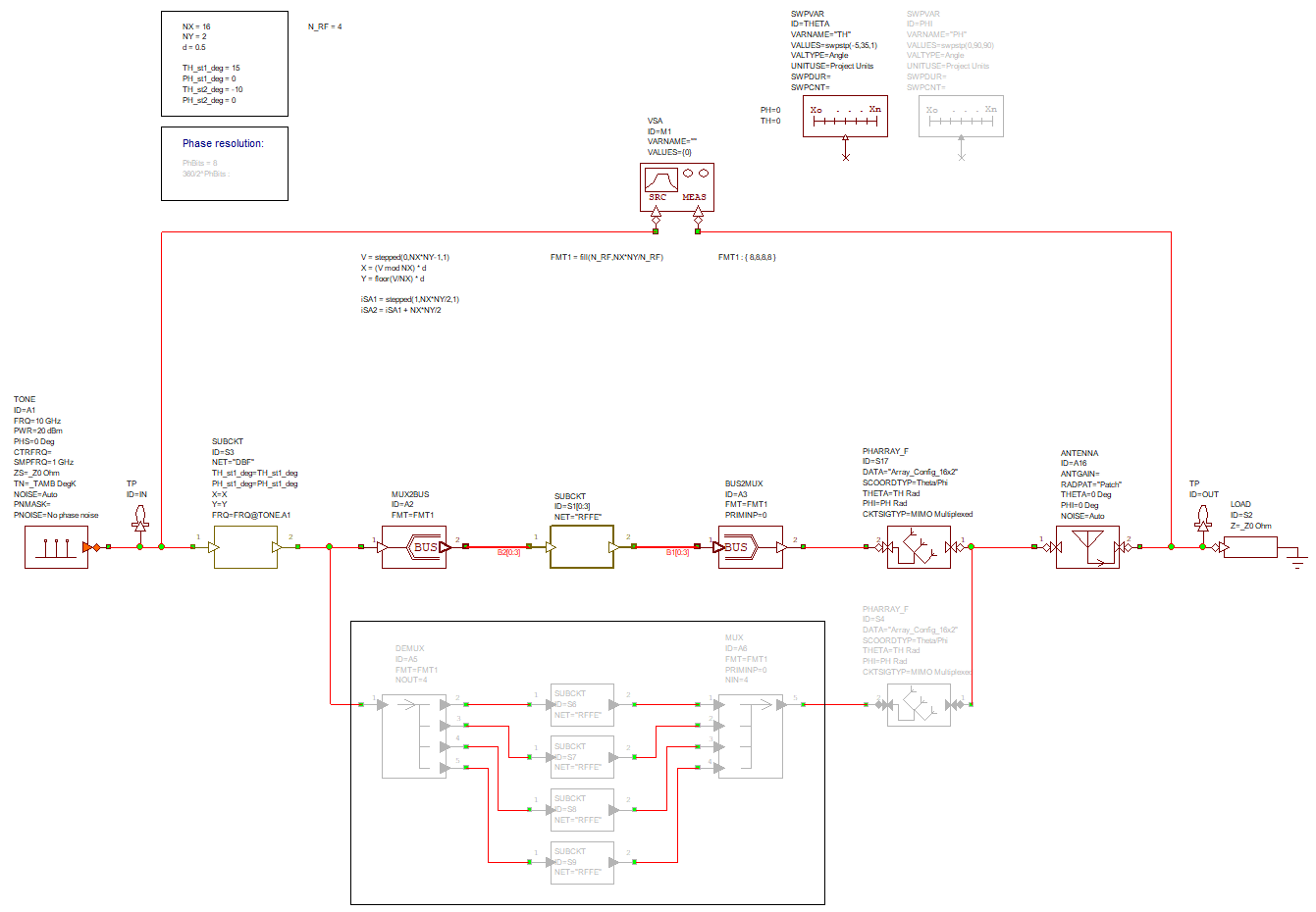
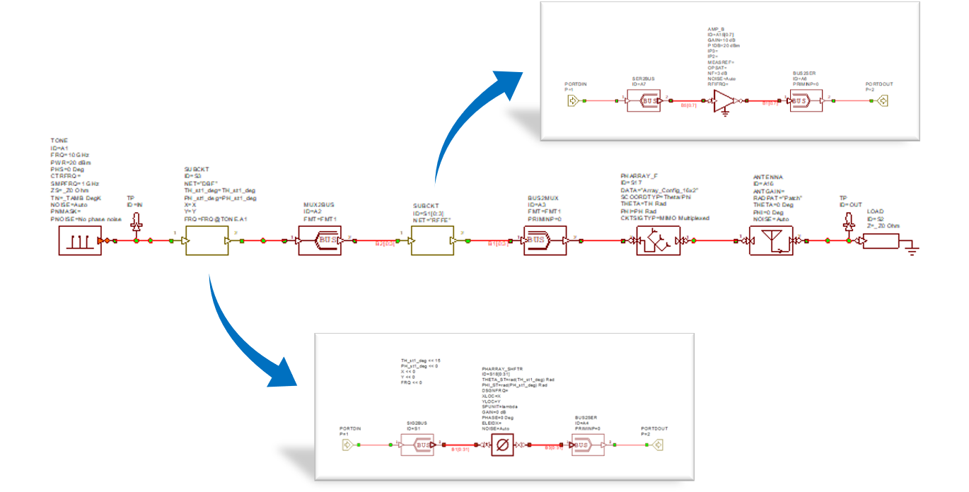
Hybrid Beamformer Design
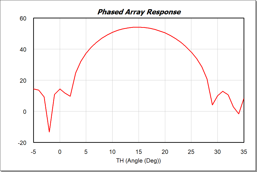
  • The signal source, a tone in this case, is first converted into a 32-element bus, passed to a digital phase shifter to apply the desired steering angle, then reconfigured into 4 8-element buses that implement the RF links.
  • The outputs are finally passed into the phased array block that applies the correct phase to each element based on the specific coordinates and direction of transmission.

Phased Array Response

The array response is measured over a range of angles and shown in the graph on the right. This project uses the VSS Time Domain simulator for this measurement.

The measurement results are stored in the project and displayed in the "Phased Array Response" graph.

Note that running the simulation takes several minutes to generate the full array response.