Go to playground home.

Layout

This page lists improvements to the Layout Editor in the AWR Design Environment.


V15


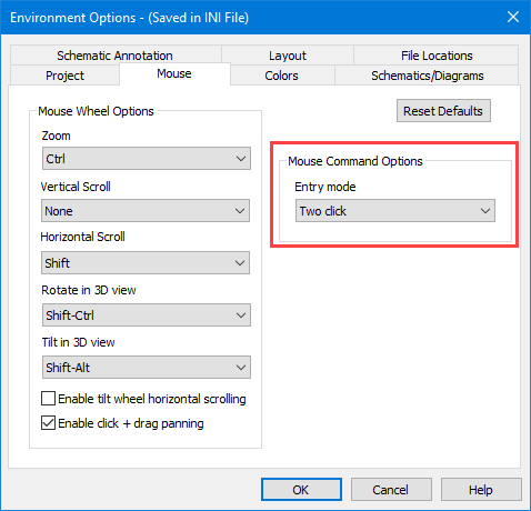
Replace Clicking-and-dragging with Two-click Data Entry Mode

This demo opens a layout playground.

License Requirements: Layout (MWO_XX5+)

  1. Choose Options > Environment Options to open the Environment Options dialog box, then click the Mouse tab.
  2. Set the Entry mode to Two click.
  3. Mouse entry is now set to two-click mode; clicking and dragging is no longer required for layout entry.
  4. In the myLayout playground, draw various layout objects to practice two-click entry mode.
    • Choose Draw > Rectangle, Circle, Polygon, Path to draw the corresponding object.
  5. Two-click entry mode also works with commands that are intuitive with the mode such as View Area, Stretch Area, and adding cutouts.
  6. To revert the Entry mode simply change it back to Click and drag.

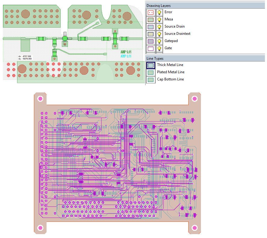
Reduce Layout Entry Errors with Full Color Layout Design Entry


Resize Rectangles, Circles, and Ellipses with Properties Dialog Box Edits


V14


This page contains improvements to the layout editor in the AWR Design Environment.

License requirements: Layout (MWO-XX5+)

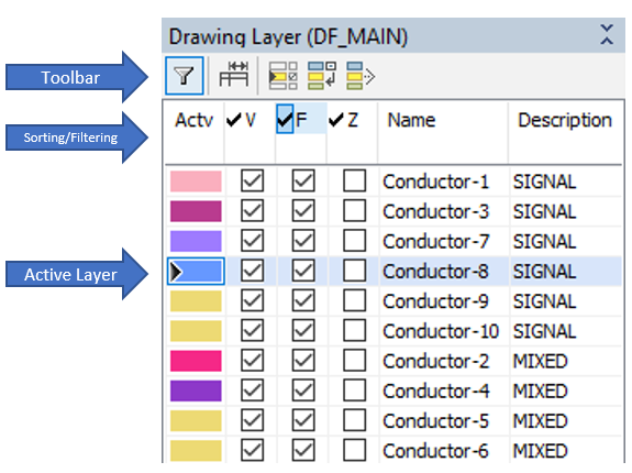
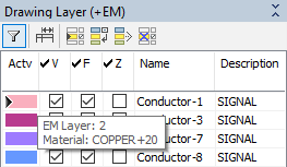
Easily control layer settings within the layout manager.

Get to Know the Drawing Layer Control

The demo opens a project a tiles a 2D layout and instruction for the user to follow.

  1. Open the Layout Manager (View -> Layout Manager).
  2. Sort the drawing layers by clicking the Name column header.
  3. Note that hovering over the toolbar buttons pops up balloon help with descriptions about the button function.
  4. Filter to only show non-signal layers by typing "!Signal" in the Description Column.
    • Make sure the Filtering is enabled on the layout manager toolbar.
    • Filtering supports the use of regular expressions.
  5. Click the Check in the V column to disable the visibility of the non-signal layers.
  6. Click the Check again to enable visibility of all of the drawing layers.
  7. Click the filter toolbar button to disable filtering.
  8. Click the Hide non-active layers toolbar button.
    • Notice the visibility is only checked for the active layer.
    • The black triangle in the Actv column represents the active layer.
  9. Click the Conductor-1 layer in the Actv column to change the active layer, and therefore the visibility.
    • Click a few other layers and note the visibility changes.

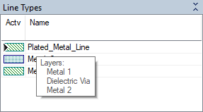
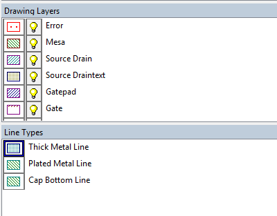
Efficiently understanding the Drawing Layers used in a Line Types.

Line Type Control

This demo tiles a 2D layout for the user.

  1. In the Drawing Layer control, make sure Hide non-active layers is toggled off.
  2. Expand the Line Types view of the layout manager.
  3. Select the Plated_Metal_Line as the active layer in the Line Types view.
  4. Hover the mouse over the Plated_Metal_Line Actv column until the tool tip opens
    • The tool tip contains the constituent layers of the Plated_Metal_Line line type.

Effortlessly interpret EM layer mapping.

EM Layer Control

This demo tiles a 2D EM layout for the user.

  1. In the drawing layer control in the layout manager select Conductor-1 as the active layer.
  2. Hover the mouse over the Actv column for the Conductor-1 row.
    • Notice the tool tip displaying the EM Layer Mapping and the Material for the drawing layer.
  3. Note that hovering over the toolbar buttons pops up balloon help with descriptions about the button function.
  4. Click the Show unmapped layers toolbar button in the drawing layer control of the layout manager.
    • A blue X means the drawing layer is not mapped to an EM layer.
    • A red X means the material used by the drawing layer is not defined.
    • The details can be seen in the tool tip by hovering over the Actv column for the entry in question.

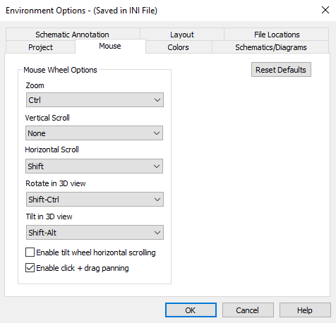
Leverage existing muscle memory with middle mouse wheel control.


V13


This page contains improvements to the layout editor in the AWR Design Environment.

License requirements: Layout

Easily interact directly with multi-layer line-types.

Save time and clicks with new layout editing commands.

Leverage the power of shape pre-processing in schematic layouts.

Comprehensively understand layout and dramatically improve visibility with 2D translucency.
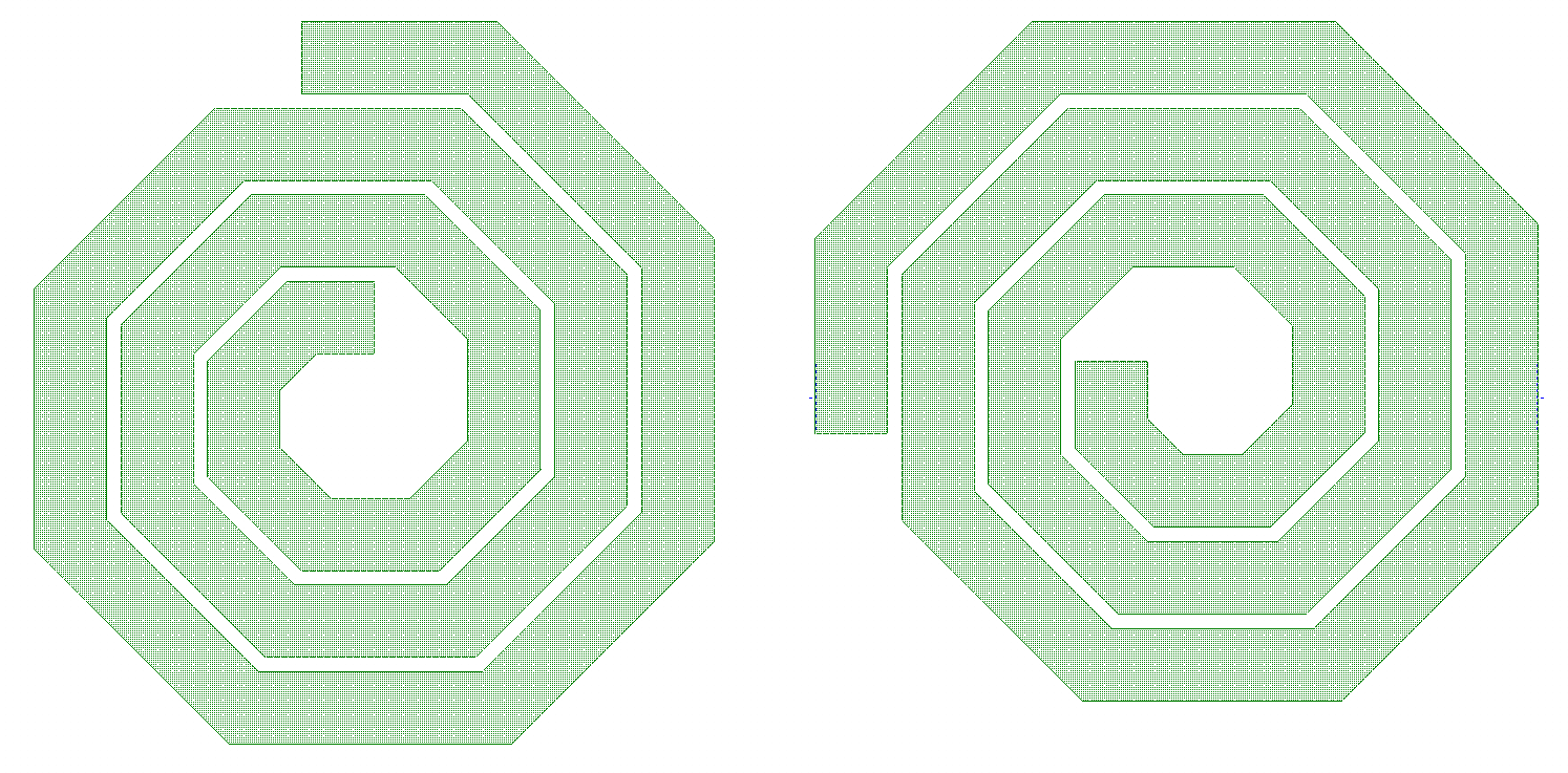

Draw with Line Types

The demo creates a new project and allows the user to select a line type and draw a shape with it.

  1. Select the Layout Manager
  2. Choose a Line Type to draw with, such as Plated Metal Line, and draw a simple shape. All drawing layers that comprise the Line Type are drawn with proper offsets.

Layout Editing Commands

Demonstrates improved layout functionality that is aimed at saving time spent creating and manipulating layout shapes.

Rotate Element/Shapes Using the Keyboard

This demo illustrates how to rotate shapes with the keyboard.

  1. Rotate the spiral inductor using CTRL + L or R arrow keys

Note: This also works for elements in a schematic or system diagram.

Execute the Same Command With a Single Click

This demo illustrates how the AWR Design Environment functions in command-repeat mode.

  1. Select the vias, and copy them with Ctrl + C.
  2. Enable command repeat mode using the new Command Repeat button on the toolbar as highlighted in the image below.
  3. Command Repeat Button
  4. Paste the vias with Ctrl + V
  5. Continue to paste the vias by single left-clicking the mouse.

Move Layout Object Relative to One Another and Without Holding the Mouse Button

This demo illustrates how to move layout objects with a reference.
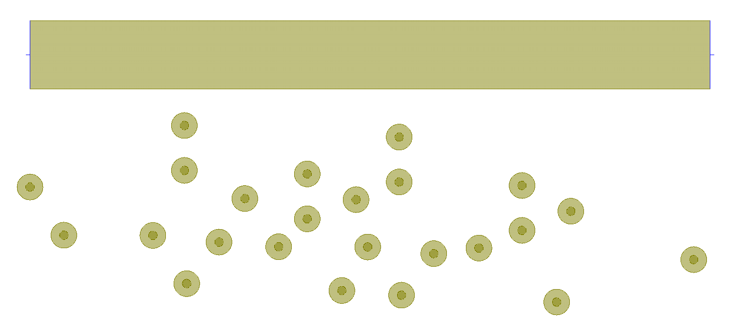
  1. Select the misplaced ground plane.
  2. Choose Edit > Move and then (using gravity snapping) click the bottom left corner of the ground place and then release the mouse button. Notice the object is still in "Move" mode.
  3. Click the bottom left corner of the PCB to align the ground plane

Create Cutouts With No Cutlines

This demo illustrates how to add cutouts to shapes in the AWR Design Environment.

  1. Right click on the selected shape and choose Add Cutout. Choose Circle.
  2. Add the circular cutout to the shape. Notice there are no cutlines.

Leverage Power of Shape Processing in Schematic Layouts

The demo opens a project and tiles a schematic to illustrate the benefits of having shape processing in schematic layout.

  1. Notice the Line Type has been merged into a single layer and the via has been turned into an octagon.
  2. The rules of the SPP Modifier can be found in its shape properties.

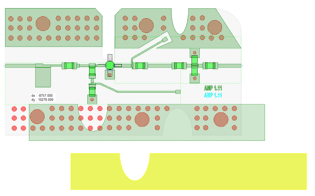
Easier 2D Layout Editing for Multi-layer Boards

The demo opens a project with a multi-layer board and has buttons to make the layout opaque or translucent.

Make the layout opaque by clicking the button.

Make the layour translucent by clicking the button.