Go to playground home.

Module

This page contains improvements to the AWR Design Environment for module designers.


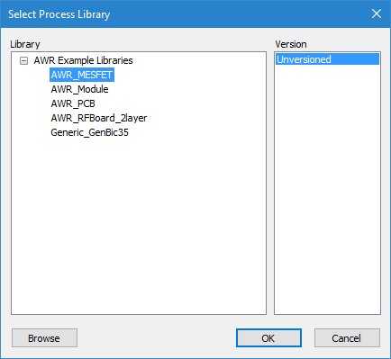
Easily Manage complex multi-technology designs (PCB, IC, LTCC, etc.).

Manage Multiple Technologies

This demo will show the improvements made to the framework to support multiple technologies in a single project.

  1. Add a second built in example library (e.g. AWR PCB) through the Project > Process Library > Add/Remove Process Library dialog. Notice the improved list of available libraries.
  2. Also, the Global Definitions document and the lpf were automatically added.
  3. Create a new schematic. Notice how you can select the LPF. Choose one and create the schematic.
  4. In the schematic options, notice how the LPF for the schematic and the Global Definitions document are set to match the process selected when creating the schematic.
  5. Add a STACKUP to the schematic. Notice how the LPF for the schematic is set to match as well.

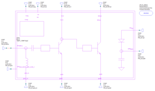
Validate designs created by users in different tools by co-simulating with Cadence Virtuoso designs.

Cadence Spectre Co-simulation

The project will open to a Schematic and Graph window and simulate.

License requirements: Translated Spectre Designs (SPS-100), Nonlinear simulator (MWO-2XX), and VSS Communication standards (VSS-350)

  1. The instance on the Schematic is an imported Spectre netlist.
  2. Note the single tone Microwave Office results and the 802.11a 36 Mpbs VSS results
  3. Imported designs are managed in PDKs so browse to Elements > Libraries > mmic_pkg > mmic_pkg and show that the translated design named mmic is available for placement.
  4. Note that the symbol was imported from Cadence using the Open Access Import/Export Wizard and that the layout is an imported GDSII file.
  5. If interested in the Spectre netlist import process choose Scripts > Demo > Import Spectre Netlist Demo and follow the script instructions.
  6. Click Done to close the script.