This page lists improvements to the AWR Design Environment related to design flows.
Minimize Test Bench Management with Measurements on Data Source Groups
The project opens to a data display page and a circuit schematic, and simulates.
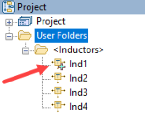
Note the special NET parameter notation in the circuit schematic matches the name of a User Folder in the Project Browser.
After simulating the item in the <Inductors> User Folder, the item with the green cross on the icon is plotted.
Click on a different inductor model to update the results from that model.
Ctrl + Click to multi-select inductor models and view multiple results.
Measurements on Data Source Groups also support always plotting results from all simulation documents (circuit schematics, netlists, data files, and others) in the group.
Use this technique to simplify test bench management, compare multiple circuit topologies, and other tasks.
Switch between Electrical and Physical Model Specifications without Leaving a Schematic
The project opens and displays the branchline coupler and its performance.
The branchline coupler design frequency is ~4.8 GHz. The goal is to tune it with the Transmission Line Calculator to a new center frequency of 3 GHz.
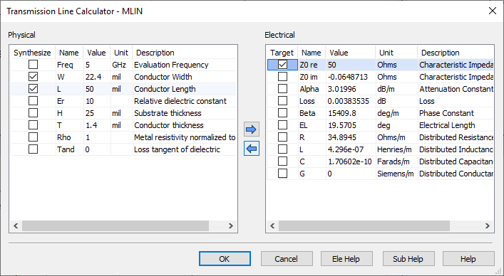
In the "BranchLineCoupler" schematic, right-click on the input MLIN.TL1 and choose Synthesize. The Transmission Line Calculator opens.
In the Physical panel, change the Freq parameter to 3 GHz.
Select the W and L parameter check boxes.
In the Electrical panel, select the Z0 re parameter check box and set the value to 50 Ohms.
Click the Left Arrow to synthesize new physical parameters based on the specified electrical parameters and the substrate in the schematic.
Repeat this process for the horizontal 0.707*Z0 line MLIN.TL3, but use the following parameters:
Change the Freq parameter value to 3 GHz.
Select the W and L parameter check boxes.
Change the EL parameter value to 90 degrees.
Change the Z0 re parameter value to 35.35 Ohms.
Repeat this process for the vertical 50 Ohm line MLIN.TL2, but use the following parameters:
Change the Freq parameter value to 3 GHz.
Select the L parameter check box.
Change the EL parameter to 90 degrees.
Simulate (F8) to center the coupler at 3 GHz. Note that the resonance is not precisely at 3 GHz because these are physical models, not ideal electrical models.
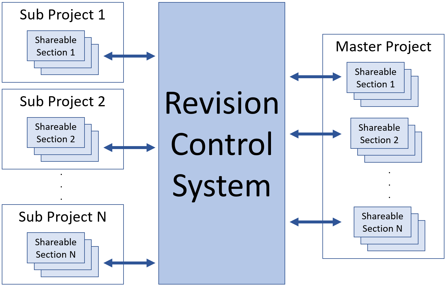
Collaborate with Other Designers and Keep Design Data Revision History
The video is viewable inline or fullscreen. Press the Play button to begin the video.
Simulate Analyst EM Structures on Linux LSF Clusters from Microwave Office
Synthesize Using Component Library or PDK parts with the Network Synthesis Wizard
Matching Network Wizard Overview
The Network Synthesis Wizard allows you to specify goals and use either ideal or vendor components to generate matching network topologies in just minutes. In this example, a PA matching network is designed to meet both PAE and output power at a fixed compression point goal.
The project opens to the "Matching Network Report" Output Equations page, and simulates.
License Requirements: Network Synthesis (SWS-100)
Open the example instance of the Network Synthesis Wizard and review the setup on each tab:
Synthesis Definition - defines the "direction" of the matching network and frequency band(s) of interest.
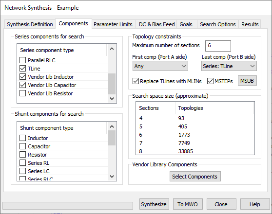
Components - defines the available series and shunt components as well as first component and last component limitations. Note that Vendor Library components are used.
Vendor components available to use in the wizard come from the Libraries that AWR is aware of. This includes any custom XML libraries, PDK components, or the online vendor libraries.
You can select a subset of components for vendor library components and store this information for future synthesis runs.
For real transmission line models, discontinuity models can be included between components for greater accuracy.
Parameter Limits - defines the parameter limits, parameter rounding, component series, etc. for each component.
Note that the L and C are limited to the E24 value table and that the MLIN values round to 1 mil.
DC & Bias Feed - defines the matching network DC path constraints and the bias injection network that the wizard should consider.
Note that because this is a PA output matching network, Port B must be a DC open to ground.
Goals - defines the measurements and goals for the synthesis. Double-click on a Measurement or Goal to see the setup.
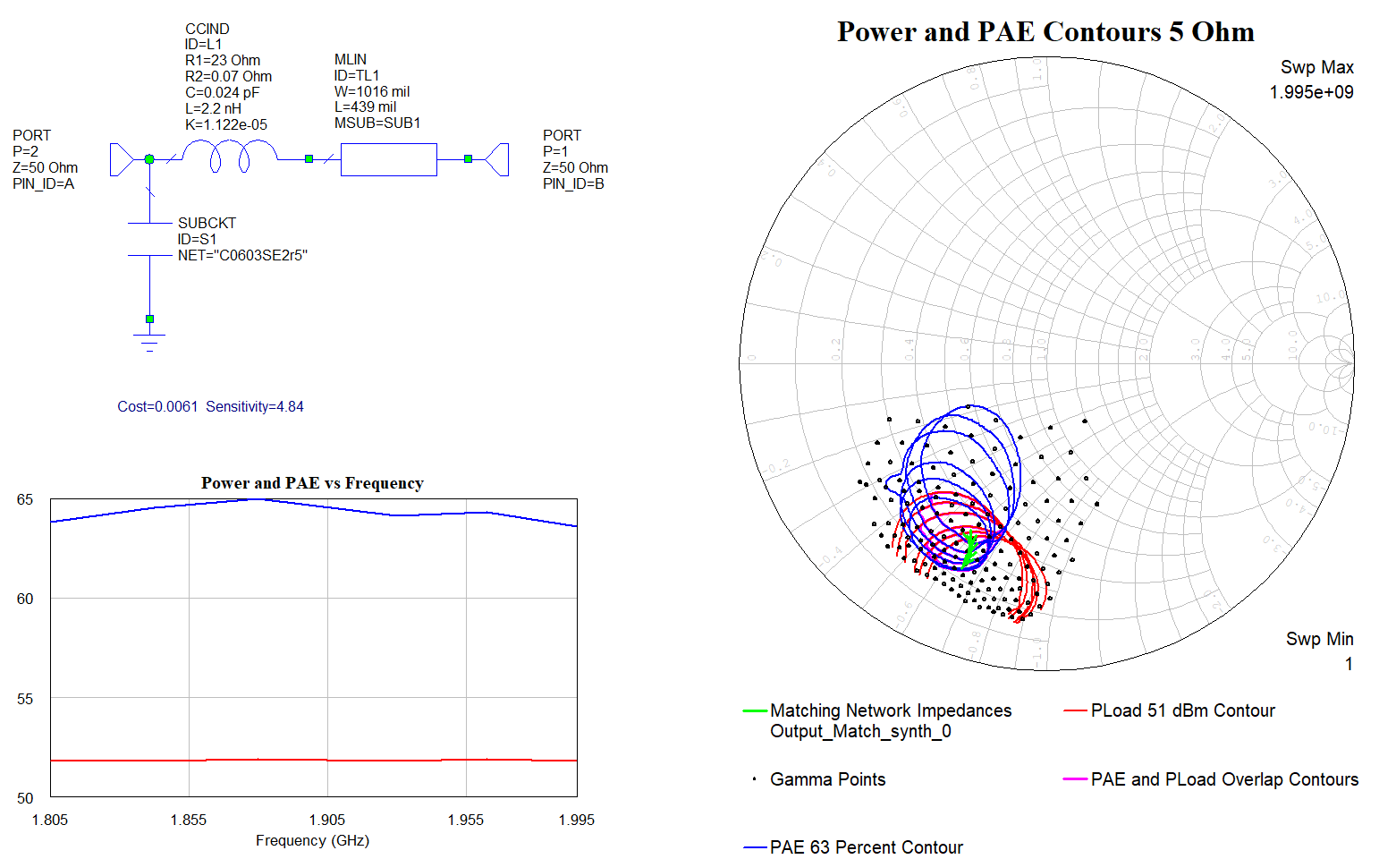
Note that the examples in this measurement use the load pull data as the source and define PAE and Output Power at 1 dB Compressed.
The goals are set up for a PAE >= 63%, an Output Power >= 51 dBm, and a 2nd and 3rd harmonic region.
Select the "HarmAreaMatch" goal and then click the View Region button to view the specified harmonic region.
The synthesis can also limit the number of unique vendor components with the CompCount measurement. This helps prioritize component reuse.
Search Options - defines advanced search options.
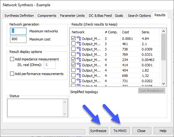
Results - shows the results from the Synthesis run and controls how many networks and what additional data is sent back to Microwave Office.
Exploring Vendor Component Selection
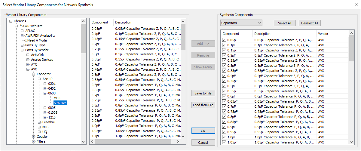
On the Network Synthesis Wizard Components tab, click the Select Components button.
The left pane of the Select Vendor Library Components for Network Synthesis dialog box lists the libraries and components available for network synthesis. This list includes any custom XML libraries, PDK components, or online vendor libraries.
The right pane of the Select Vendor Library Components for Network Synthesis dialog box displays the components selected for the current network synthesis. Selections can be saved and loaded for convenience.
Components are also filtered by type. For example, Resistor, Inductor, or Capacitor. In this synthesis only inductors and capacitors are selected.
Synthesizing and Sending Results to Microwave Office
NOTE: This synthesis takes a few minutes to run so there are results already saved in the project. To start a new synthesis, click the Synthesize button, otherwise skip to the next step to use the pre-synthesized results.
For an example that synthesizes more quickly, see the example on the design flow page.
When the synthesis is complete (or if you skipped the synthesis step) click the To MWO button to send the results to Microwave Office.
Click OK on the Overwrite Options dialog box.
Click Close to close the wizard.
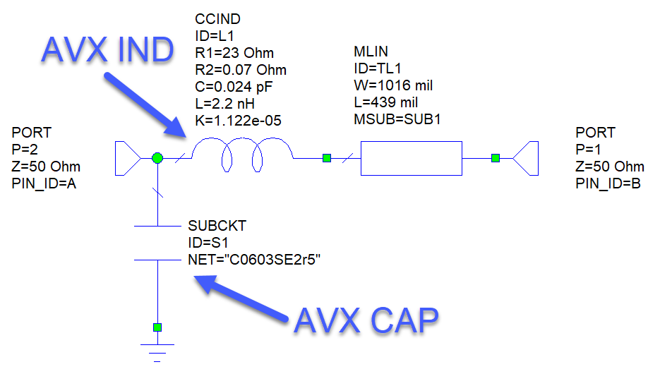
When the synthesis is performed and vendor components are used, all necessary model information is imported into the project. In this instance, the S-parameter data files are used for the AVX 0603 inductors and capacitors.
Exploring Results
All of the generated networks are in the Microwave Office <Output_Match_synth> User Folder in the Project Browser.
Click on the individual networks under the User Folder to see the results from the networks.
The graph results update to show response with the selected network, and the displayed schematic updates to show the selected networks.
The matching networks use components from the AVX library of parts from the online vendor library.