Go to playground home.

Antenna

This page lists improvements to the AWR Design Environment for antenna designers.


V15


Easily Quantify and Optimize Antenna Performance Metrics
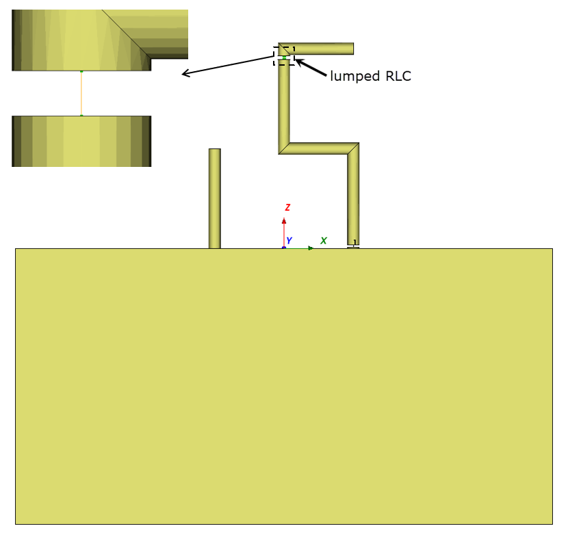
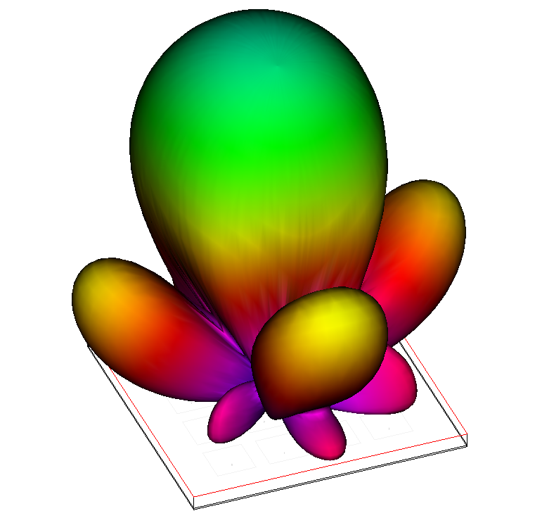

Analyze antenna performance

The project opens and simulates a 4x4 path array antenna.

License requirements: Layout and AXIEM (MWO_105+, XEM_001, XEM_100 or TOK_100)
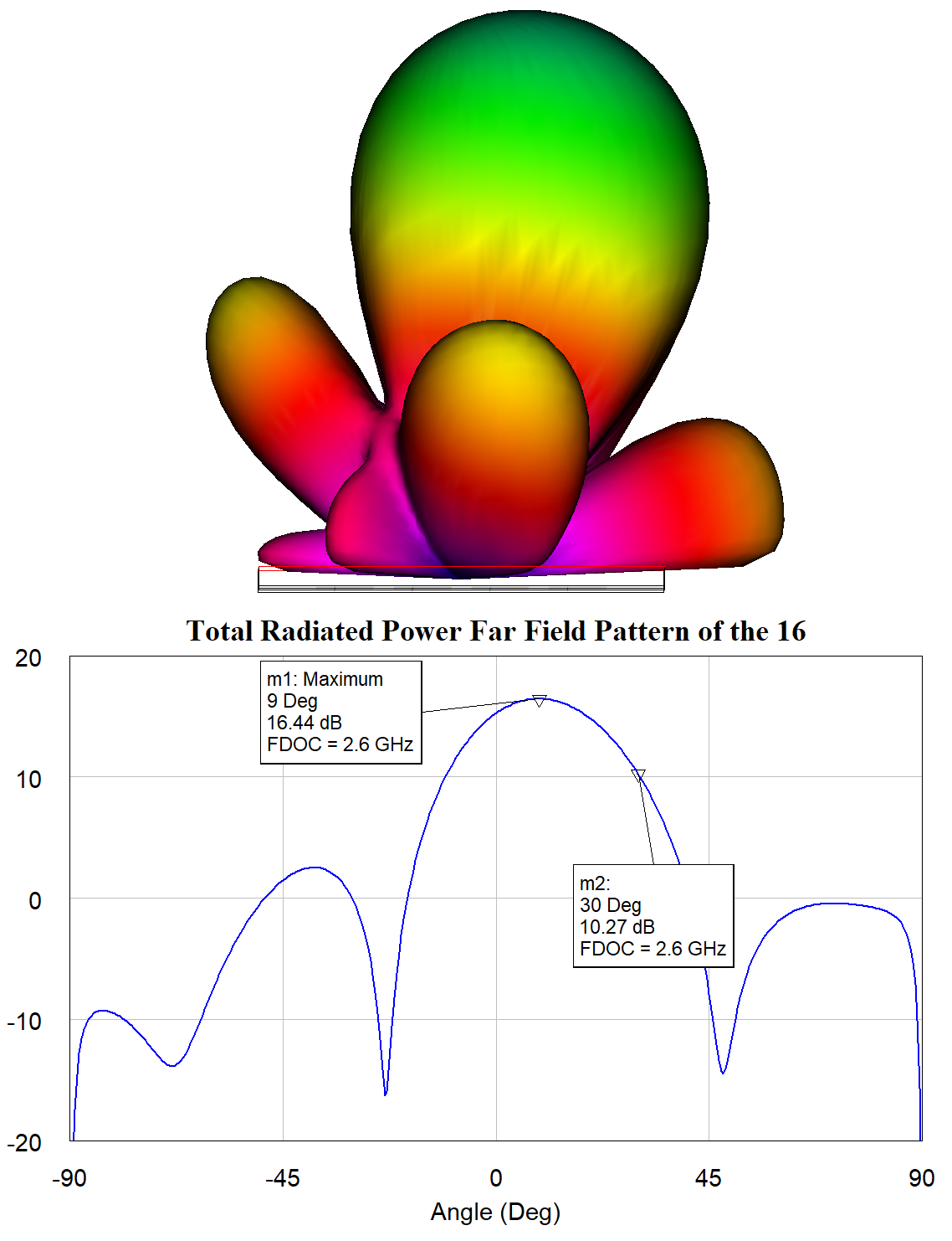
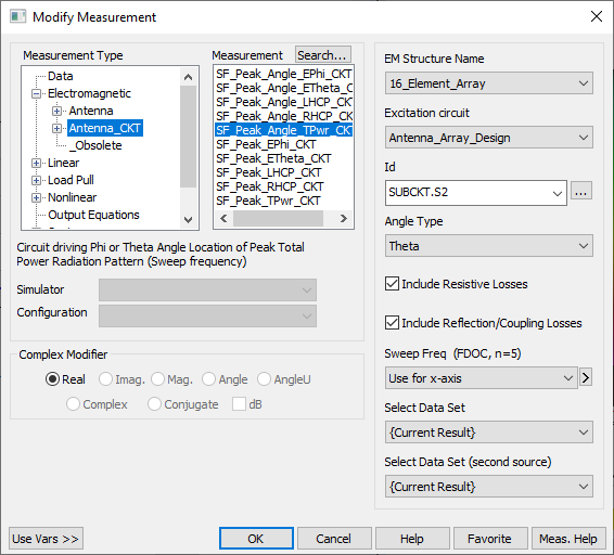
  1. In the "Principal Plane Cut Total Power" graph; note the principal plane cut; the steering angle (theta) is 9 degrees at 2.6 GHz.
  2. Rotate the 3D View of the antenna so the orientation matches that of the Principal Plate Cut Total Power by pressing the Back button on the EM 3D Layout toolbar.

Learn about new PEAK measurements

An additional graph opens which contains a measurement for the theta angle of peak power.

  1. In the "Peak Theta Versus Frequency" graph legend, right-click the Peak Theta measurement and choose Modify Measurement.
  2. Note the new class of PEAK measurements. These dimension-reducing measurements allow you to analyze antenna performance across a frequency range.

Change the theta angle with optimization

An optimization goal is added to the "Peak Theta Versus Frequency" graph.

  1. The current peak theta angle is 9 degrees. The optimization goal is set up to steer the beam to 45 degrees.
  2. The voltage magnitudes and phases presented to the antenna are set up to be optimizable.
  3. Set the Optimization Method to Discrete Local Search and the Maximum Iterations to 50.
  4. Click the Analyze button before proceeding to ensure the 3D patterns update during optimization.
  5. Click Start on the Optimizer and watch the antenna pattern shift from 9 degrees to 45 degrees.
  6. NOTE: The variables being optimized are in a schematic which is driving the EM structure. The resulting antenna patterNs are dependent on the voltage magnitudes and phases presented to the EM structure from the schematic.

Directly Simulate and Model within an Antenna

  • Directly simulate antenna loading, matching networks, and model frequency-dependent circuit components within an antenna
  • Simulate matching networks that are embedded in the antenna without the need for additional ports and circuit simulations.
  • Model frequency-dependent components in the antenna simulation to design reconfigurable or more broadband antennas.

V14


This page contains improvements to the AWR Design Environment for antenna designers.

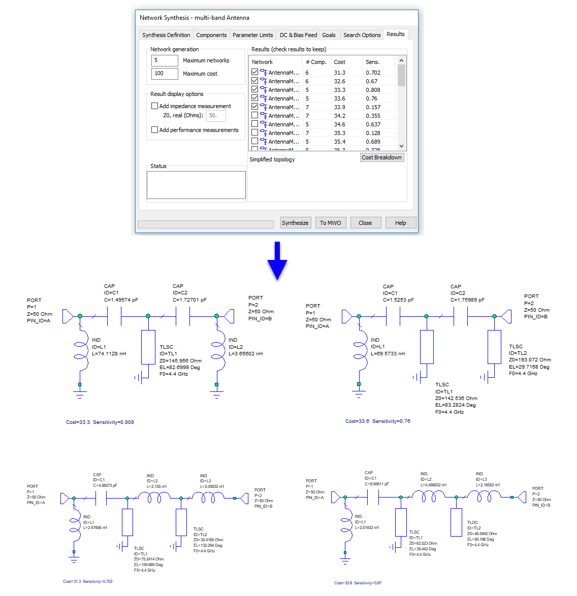
Jump-start matching network design using the Network Synthesis Wizard.
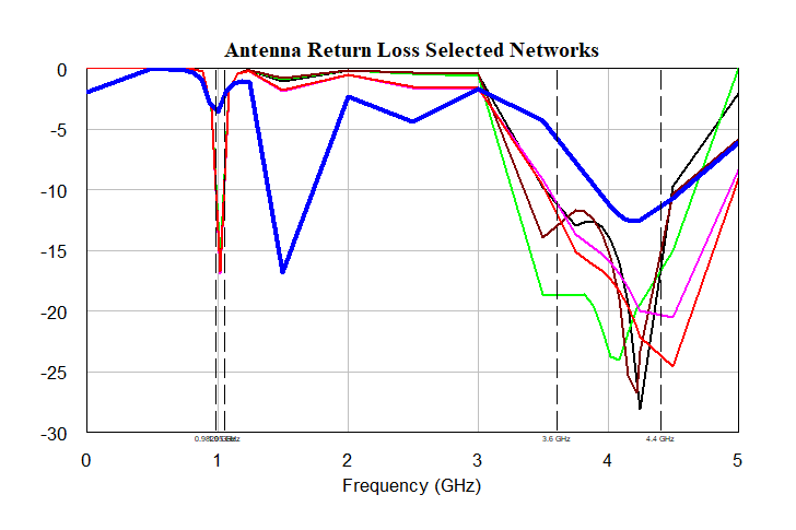

Matching Network Wizard Overview

The Network Synthesis Wizard allows the user to specify goals and components to generate matching network topologies in a matter of minutes. In this example a multi-band antenna matching network is designed to meet return loss goals in two different frequency bands.


The project will open to show the Antenna Synthesis Report Output Equations Page and simulate.

Additional Network Synthesis Wizard examples can be found on the pa and design flow pages.

License requirements: Network Synthesis (SWS-100)

  1. Open the multi-band Antenna instance of the Network Synthesis Wizard and review the setup on each tab
    • Synthesis Definition - defines the "direction" of the matching network and frequency band(s) of interest.
    • Components - defines the available series and shunt components as well as first component and last component limitations.
    • Parameter Limits - defines the parameter limits, parameter rounding, component series, etc. for each component
    • DC & Bias Feed - defines the matching network DC path constraints and the bias injection network that the wizard should consider.
    • Goals - defines the Measurements and Goals for the synthesis. Double click on a Measurement or Goal to see the setup.
      • Note that the goal is to make mismatch loss zero in each of the two bands of interest.
    • Search Options - defines advanced search options.
    • Results - shows the results from the Synthesis run and controls how many network and what additional data is sent back to Microwave Office.

Synthesizing and sending results to Microwave Office

  1. NOTE: This synthesis takes a few minutes to run so there are results already saved in the project. However, if interested, push the Synthesize button to start a new synthesis. Otherwise, skip to the next step to use the already synthesized results.
    • If you'd like to see an example that synthesizes more quickly check out the example on the design flow page.
  2. When the synthesis is complete (or is you skipped the synthesis step) push the To MWO button to send the results to Microwave Office.
  3. Push the OK button on the Overwrite Options dialog.

Exploring results

  1. All of the generated networks have been sent to Microwave Office and placed in the <AntennaMatch_synth> User Folder in the Project Tree.
  2. Click on the synthesized networks under the User Folder to see the results from the networks.
  3. Note that the Graph results update to show response with the selected network and the displayed schematic updates to show the selected networks.

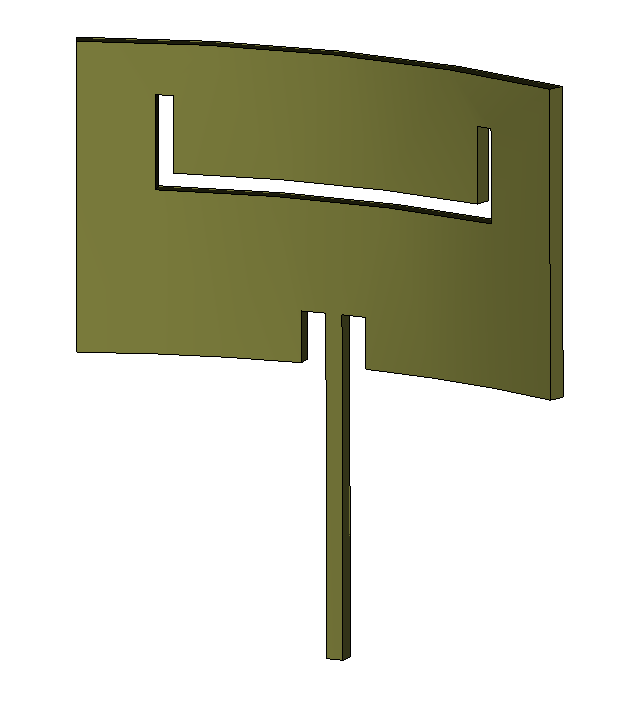
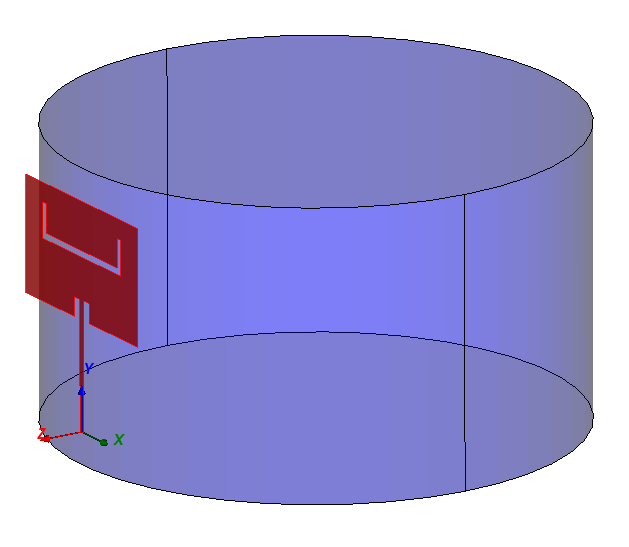
Easily create and analyze conformal antennas.


Wrapping a Sheet Around a Cylinder

The project will open with a structure set up and ready to make the antenna conformal.

License requirements: Analyst (ANA-001)

  1. Right-click on the Conformal Antenna Example 3D EM structure and choose Open in 3D Editor.
  2. Select Modify Solids -> Wrap Sheet.
    • Select the antenna and press ENTER
    • Select the Cylinder and press ENTER
    • Select OK to accept the default properties for the resulting wrapped shape

Thickening a Sheet

  1. Choose Modify Solids -> Thicken Sheet.
    • Select the antenna and press ENTER
    • Select OK to accept the default thickness and properties.

AntSyn Antenna Synthesis Improvements

Note that no active content demo is available for this capability.

More information can be found on our website or by contacting your local AWR sales representative to arrange a demo.

  • Synthesize antennas constrained to an arbitrary user-defined volume.
  • Quickly import synthesized antennas into the AWRDE for further analysis.
  • Over 100 new antenna geometries have been added to the synthesis options.
  • Find the antenna style you want more quickly with filtering and list views.
  • Synthesize high performance antenna arrays with fencing elements and shaped ground planes.
  • Understand antenna performance better before exporting it to the AWRDE.

V13


This page contains improvements to the AWR Design Environment for antenna designers.

Note that no online demo is available for this capability.

More information can be found on our website or by contacting your local AWR sales representative to arrange a demo.

Synthesize antennas or antenna elements from easy-to-set-up specifications.

Analyze and compare results using your favorite EM tools.